Complete Installation Manual for Q-SUN Photovoltaic Modules
Document number: QN3-CX-TD-046
Manufacturer: QSUN SOLAR (Jiangsu) CO., LTD.
Version: A0
Approver: Rongyuan Gu
Auditor: Rongyuan Gu
Editor: Guangyao Zhang
Issued: 2025-03-03
Executed: 2025-03-03
Version Change History Table
| Version | Page | Reason | Content | Modification date | Modified By |
|---|---|---|---|---|---|
| A0 | 22 | New release | New release | 2025.03.03 | Rongyuan Gu |
1 Introduction
Firstly thank you very much for choosing QSUN PV modules!
This installation manual covers key electrical and mechanical installation information, so please be fully aware of the information before installing QSUN modules. In addition, this manual also covers some safety information that you shall get familiar with. All contents in this manual are intellectual properties of QSUN which originates from long term of technical exploration and experience accumulation of QSUN.
This installation manual does not entail any explicit or implicit quality warranty and does not stipulate on compensation schemes for losses, module damages or other costs caused by or related to module installation, operation, utilization and maintenance process. If patent rights or the third party rights are infringed by use of modules, QSUN will not take any responsibility. QSUN reserves the rights for modifying product manual or installation manual without notice in advance.
WARRANTY NOTICE. If customers fail to install modules as per requirements set forth in this manual, the quality warranty provided for customers during sales will become invalid. In addition, suggestions in this manual are to improve safety of module installation, which are tested and proved by practices. Please provide this manual to PV system users for reference and advise them of safety, operation and maintenance requirements and suggestions.
2 Laws and Regulation
Mechanical and electrical installation of PV modules shall follow proper regulations such as electric law, building law and electric connecting requirements. These regulations vary with different installation sites, such as building roofing installation, vehicle-mounted application and etc. Requirements may also vary with DC or AC system, difference installation system voltage. Please contact local authorities for specific clauses.
3 General Information
3.1 Modules identification
Each module is pasted with 3 labels providing information below:
Label: It describes product type, standard rated power, rated current, rated voltage, open circuit voltage, short circuit current under testing conditions, certification indicator, maximum system voltage, etc.
Serial No.: Each module has a unique serial number which is solidified inside the module permanently and it can be seen from front top of the module. Each serial number is put in before laminating of the module. In addition, you can find the same serial number on the module label.
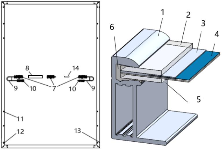
Figure 1. Regular modules Mechanical drawing
| No. | Part | No. | Part | No. | Part | No. | Part |
|---|---|---|---|---|---|---|---|
| 1 | Frame | 2 | Glass | 3 | EPE/EVA | 4 | Solar Cell |
| 5 | Back Glass | 6 | Silica Gel | 7 | Junction Box | 8 | Label |
| 9 | Cable | 10 | Connector | 11 | Mounting Hole | 12 | Grounding Hole |
| 13 | Drain Hole | 14 | Bar Code |
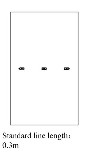
(Please refer to section 3.2 for the location of the junction box. The specific version is subject to the corresponding specification.)
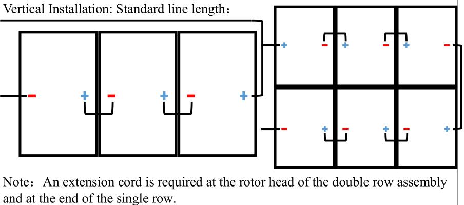
3.2 Junction Box Location and Recommended Wiring Method
| Junction Box Location Icon | Recommended Wiring Method |
|---|---|
 |
 |
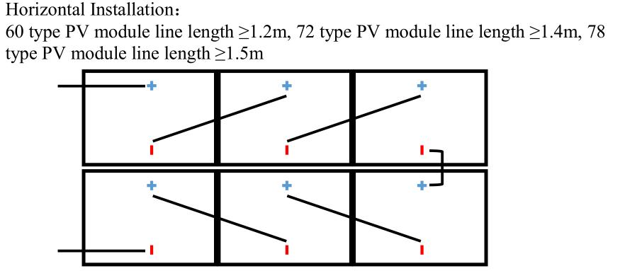 |
3.3 Regular Safety
The application level of QSUN Solar module is Class Ⅱ, which can be used in systems operating at > 50V DC or >240 W, where general contact access is anticipated;
When the module is installed on roof, it is necessary to take the overall fire rating of the finished structure as well as later overall maintenance into account. The roofing PV system shall be installed after assessment by construction experts or engineers and with official analysis results for the entire structure. It shall be proved capable of supporting extra system bracket pressure, including PV module weight.
SAFETY WARNING. For your safety, please do not work on the roof without safety protective measures which include but not limited to fall protection, ladder or stair and personal protective articles.
SAFETY WARNING. For your safety, please do not install or handle modules in unfavorable conditions including but not limited to strong wind or gust, damp or sandy roofs.
3.4 Electrical Performance Safety
DANGER — ELECTRIC SHOCK OR BURN. PV modules can produce DC current under illumination, any contact of the exposed metal of the modules connection wires may result in electrical shock or burn. Any contact of 30V or larger DC Voltage can be fatal.
In case of no connected load or external circuits, modules can still produce voltage. Please use insulation tools and wear rubber gloves when operating modules in the sunlight.
PV modules does not have switch. PV modules can only stop operating when they are kept from sunlight or covered by cloth, hard board or light-proof materials or when front side of modules are placed on smooth and flat surfaces.
To avoid electric arc or electric shock hazards, please do not break down electric connection in loaded conditions. Wrong connections will also lead to electric arc or shock. Keep connectors dry and clean and make sure that they are in good operating condition. Do not insert other metals into the connectors or carry out electric connection by whatever means.
Snow and water in surrounding environments will intensify light reflection and lead to increase of output current and power. And module voltage and power will increase under low temperature condition.
If module glass or packaging materials are damaged, please wear personal protective articles and then isolate modules from the circuit.
Any modules related works are only allowed in dry conditions by means of dry tools. Do not operate when modules are wet unless you wear the proper electric shock protection articles. Please follow the cleaning requirements in this manual when cleaning modules.
3.5 Operation Safety
- Do not open QSUN Package in transportation and storage process unless the modules arrive at the installation site.
- Do not damage the package and do not fall packaged modules.
- Do not exceed the highest layer limit indicated on the packaging carton when piling modules up.
- Put packaging carton in the ventilated, rain-proof and dry places before unpacking of modules.
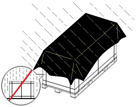
- Open QSUN’s packaging carton following unpacking instructions.
- Do not lift the module by holding the junction box or wires in any cases.
- Do not stand or walk on modules.
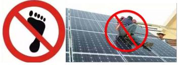
- Do not drop one module onto another.
- To avoid glass damage, do not put heavy objects on module glass.
- Be careful when placing modules on a surface and at corners in particular.
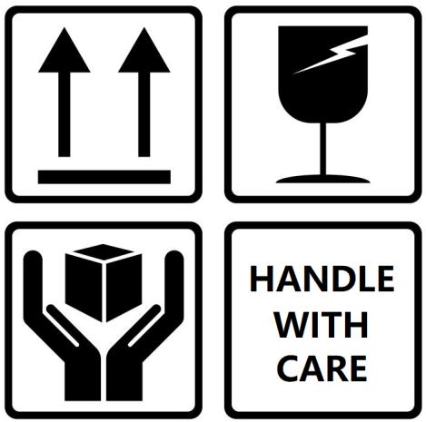
- Do not try to unpack the module or remove nameplate or parts of modules.
- Do not paint surface of modules or apply any other glues.
- Do not damage, grad or scratch back film of modules.
- Do not drill frame of modules, which may reduce frame loading capacity or lead to frame corrosion.
- Do not scratch anodic coating of aluminum alloy frame except for grounding connection. Scratch may lead to frame corrosion and reduce frame loading capacity.
- Do not repair glass or modules whose back film is damaged on your own.
3.6 Fire Safety
Please consult local laws and regulations before installing modules and abide by requirements on building fire protection. According to the corresponding certification standards, the fire rating of the components of QSUN is Class C.
The roof should be coated by a layer of fireproof materials with suitable fire protection rating for roofing installation and make sure that the back plate and the mounting surface are fully ventilated.
Difference roofing structures and installation modes will affect fireproof performance of buildings. Improper installation may lead to the risk of fire.
FIRE SAFETY REQUIREMENT. To guarantee roof fire rating, the distance between module frame and roof surface must be >=10cm. (4in) Adopt proper module accessories such as fuse, circuit breaker and grounding connector according to local regulations.
Please do not use modules if there are exposed inflammable gases nearby.
4 Installation Conditions
4.1 Installation Site and Working Environment
The modules can only be used on earth but not in outer space.
Do not manually focus sunlight with mirrors or magnifying glass onto modules. Artificially concentrated sunlight producing a PV module’s current above the value reported on the nameplate shall not be directed onto the front side or the back side of the PV module.
QSUN modules shall be installed on proper buildings or other appropriate places (such as ground, garage, building outer wall, roof, PV tracking system) but shall not be installed on any vehicles.
It is possible that modules installed with restricted airflow are not allowed for use in some hot locations, depending on system design parameters. Installers should assess if the system design at a specific geographic location will result in a 98th percentile module operating temperature greater than 70 °C, and must consider these factors in design of systems (refer to IEC TS 63126 for more information).
Do not install modules at places that are possible to be flooded.
QSUN suggests that modules be installed in the working environment with the temperature of -40 ℃ to 40 ℃ which is the monthly average highest and lowest temperature of the installation sites. Make sure that installed modules do not suffer wind or snow pressure that exceeds the permissible maximum load limit. The 98th percentile module operating temperature is 70 °C.
Modules shall be installed in places free from shadows throughout the year. Make sure there are no light-blocking obstacles in the installation sites.
A photovoltaic module is likely to experience conditions that produce higher current and/or voltage than reported at standard test conditions. Factors to consider include module temperature and front side irradiance (and, for bifacial modules, ground or roof albedo, row spacing, and installation height). Accordingly, the values of VOC and ISC (or for bifacial modules, ISC-aBSI) marked on this PV module should be multiplied by a factor of 1.25 when determining voltage and current ratings for components connected to the PV output.
The safety factor of 1.25 given for the minimum voltage rating of the components in the example statement above may be modified during the design of a system according to the minimum temperature of the location of the installation and the temperature coefficient for VOC. The safety factor of 1.25 given for conductor current ratings values for ISC (or for bifacial modules, ISC-aBSI) may be adjusted based on the maximum values of irradiance incident on the front side of the module (and the rear side for bifacial modules). To this purpose, a full simulation for the specific location and module orientation (and for bifacial modules, ground albedo, row spacing and installation height) is required. Further guidance for the choice of a safety factor other than 1.25 is given in IEC 62548.
- Carry out lightning protection for modules installed in places with frequent lightning and thunder.
- Do not install modules in places with possible inflammable gases.
- Modules cannot be used in environments with too much hails, snows, flue gas, air pollution and soot or in places with strong corrosive substances such as salt, salt mist, saline, active chemical steam, acid rain, or other substances corroding modules, affecting module safety or performance.
- Please take protective measures to ensure reliable and safe installation of modules in severe environments such as heavy snow, cold and strong wind or islands close to water and salt mist or deserts.
QSUN modules have passed the IEC61701 salt spray corrosion test, but the corrosion may still occur on where the modules frame is connected to the bracket or where the grounding is connected. QSUN modules can be installed 50m–500m away from the ocean side, but stainless steel or aluminum material are needed to be used in where contacting PV modules and apply anti-corrosion measurement on the connection point. Please refer to the QSUN Seaside Installation Manual for further detail.
4.2 Selection of Tilt Angles
Tilt angle of modules: Included angle between module surface and horizontal surface; the module will obtain the maximum power output in direct facing of sunlight.
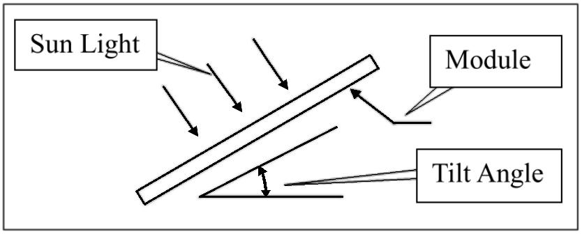
Modules are preferred to be south-facing in the north hemisphere and north-facing in the south hemisphere.
Please refer to standard modules installation guideline or suggestions from experienced PV module installer, for the specific installation angle.
QSUN suggests that module installation tilt angle be no less than 10° so module surface dust can be washed away easily by rainfall and times of cleaning can be reduced. And it is easy for ponding to flow away and avoid water print on the glass due to long time of water ponding which may further affect module appearance and performance.
The QSUN modules connected in series should be installed with the same orientation and tilt angle. Difference orientation and tilt angle may result in differ received solar irradiation and result in output power loss.
If the QSUN modules are used in Stand-alone System, the tilt angle should be calculated based on seasons and irradiation to maximize the output power. If the modules output power meets the acquired load under the period of the worst irradiation in the year, the modules should be able to meet the load of entire year. If the QSUN modules are used in Grid-connected System, the tilt angle should be calculated based on the principle to maximize the yearly output power.
5 Mechanical Installation
5.1 Regular Requirements
Make sure that module installation mode and bracket system can meet the expected load, which is requisite assurance that the bracket installer must provide. Installation bracket system shall be tested and inspected by the third party testing institution with static mechanical analysis capacity in accordance with local national standards or international standards.
- Module bracket shall be made from durable, corrosion resistant, ultraviolet proof materials.
- Modules shall be fixed on the bracket solidly.
- Use higher brackets in places with heavy snow accumulation so the lowest point of modules will not be covered by snow for a long time. In addition, make the lowest point of modules high enough so as to avoid shading of vegetation and woods or damage of sands and stones.
- If modules are installed on brackets parallel to the roof or wall, the minimum gap between the module frame and the roof/wall shall be 10cm for air ventilation so as to prevent module wire damage.
- It is forbidden to drill holes in the glass and frame of the component without the permission of QSUN.
- Make sure the building is suitable for installation before installing modules on roof. Moreover, seal permeable parts properly to prevent leakage.
- The module frames can appear thermal expansion and cold contraction so the frame interval between two adjoining modules shall be >= 10mm.
- Make sure that back plate of modules will not in contact with bracket or building structures that can pierce into the inside of the modules, especially when the module surface is imposed by pressure.
STATIC LOAD REQUIREMENT. Maximum static load of the PV module by: front 8400Pa and back 6600Pa for model with 2.8mm glass, front 3600Pa and back 2400Pa for model with 1.6mm glass, front 5400Pa and back 2400Pa for other models. These values can vary depending on installation method of the modules (please refer to the following installation guidance), the described load in this manual is for the test load. Note: on the basis of IEC61215-2021 installation requirements, when computing the corresponding maximum design load, need to consider the safety factor of 1.5 times.
Modules can be installed horizontally or vertically. When installing the components, be careful not to block the drain hole of the frame.
5.2 Monofacial assembly mechanical installation
Module and bracket system connection can be realized by clamps.
WARRANTY NOTICE. Installation shall follow the demonstration and suggestions below. If installation mode is different, please consult QSUN and obtain approval. Otherwise, modules may be damaged and quality warranty will become invalid.
5.2.1 Install Modules by Mounting Holes
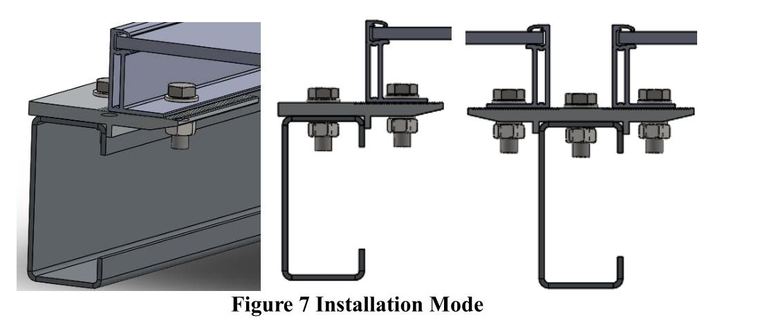
Make use of bolts to fix modules on the bracket through mounting holes on the back frame. See details in Figure 7.
| Accessories | Model | Material | Note |
|---|---|---|---|
| Bolt | M8 | Q235B/SUS304 | Accessories material selection should base on local environment. |
| Washer | 2*8 | Q235B/SUS304 | Accessories material selection should base on local environment. |
| Spring Washer | 8 | Q235B/SUS304 | Accessories material selection should base on local environment. |
| Nut | M8 | Q235B/SUS304 | Accessories material selection should base on local environment. |
| Accessories | Model | Material | Note |
|---|---|---|---|
| Bolt | M6 | Q235B/SUS304 | Accessories material selection should base on local environment. |
| Washer | 2*6 (6.4*18-1.6 ISO 7093) | Q235B/SUS304 | Accessories material selection should base on local environment. |
| Spring Washer | 6 | Q235B/SUS304 | Accessories material selection should base on local environment. |
| Nut | M6 | Q235B/SUS304 | Accessories material selection should base on local environment. |
(Suggest 1) M8 bolt tightening torque range: 16N•m-20N•m; M6 bolt tightening torque range: 5N•m-12N•m;
(Suggest 2) When using QSUN 30mm (30H) height frame assembly, it is recommended to select L ≤ 20mm length fasteners. (If you have a special model, you can consult QSUN customer service);
5.2.2 Use clamps to install modules
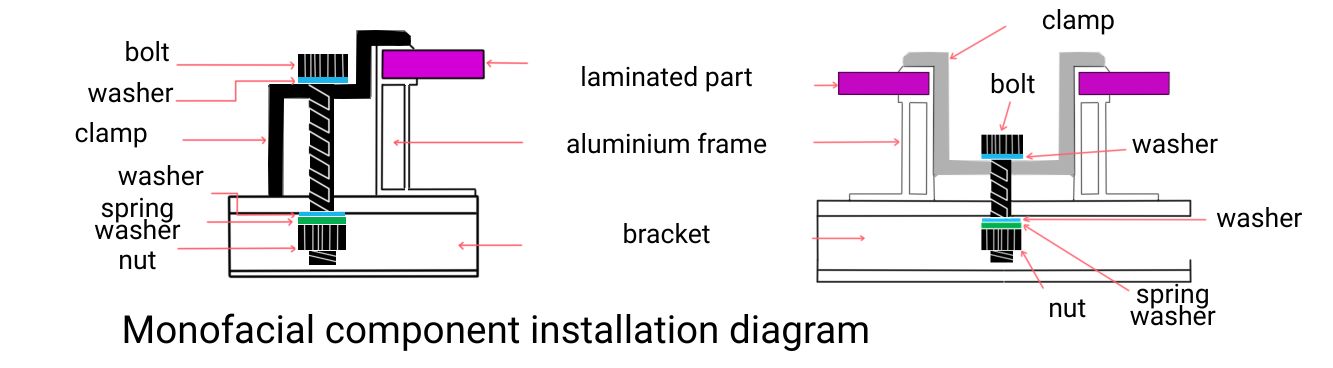
The assembly can be mounted using a dedicated fixture, as shown in Figure 5.
Under no circumstances should the fixture touch the glass or deform the frame of the component.
The surface of the fixture that is in contact with the front of the frame must be smooth and flat, otherwise the frame will be damaged and the component will be damaged.
Be sure to avoid the shadow blocking effect of the fixture. The drain hole cannot be blocked by the fixture. The fixture must maintain an overlap of at least 8 mm but no more than 11 mm with the frame of the assembly (you can change the cross section of the fixture if the assembly is securely installed).
5.2.3 One-sided component installation diagram
Screw clamp mounting: The static load on the largest back of the module is 2400Pa (equivalent to wind pressure), and the maximum static pressure on the front is 5400Pa (equivalent to wind pressure and snow pressure).
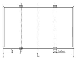
D = 1/4 L
6 Electrical installation
6.1 Electrical Performance
Module electric performance parameters such as Isc, Voc and Pmax nominal values have ±3% error with those under standard testing conditions of: irradiance of 1000 W/m², cell temperature of 25℃ and air mass of AM1.5.
When modules are in series connection, the final voltage is sum of that of the single module. When modules are in parallel connection, the final current is sum of the single module as below Figure 10 shows. Modules with different electric performance models cannot be connected in series.
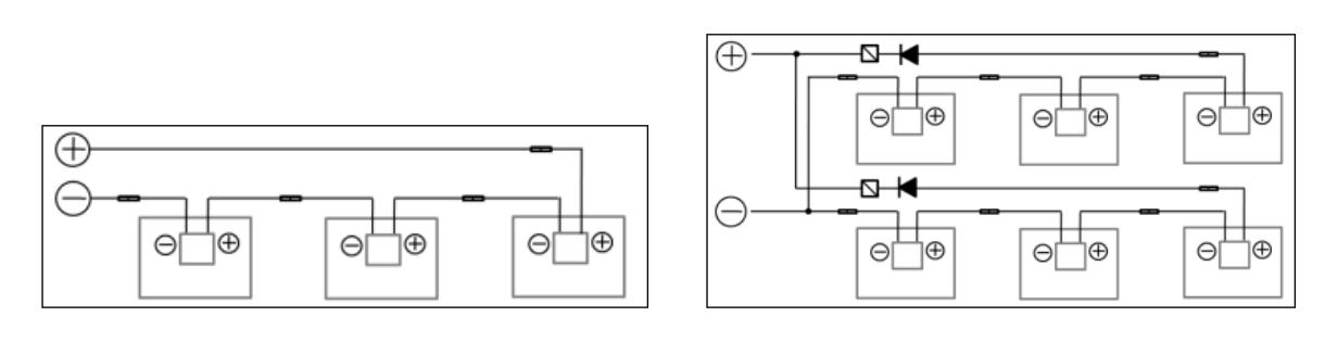
Figure 10: Series connection and parallel connection circuit diagram
The number of modules in series connection in each strand shall be calculated according to relative regulations.
The open circuit voltage value under the expected lowest temperature shall not exceed the maximum system voltage value stipulated for modules and other values required by DC electric parts. (QSUN modules maximum system voltage is DC1500V fuse rating 30A—actually system voltage is designed based on the used modules model and inverter.)
Under normal conditions, a photovoltaic module is likely to experience conditions that produce higher current and/or voltage than reported at standard test conditions. Accordingly, the values of Isc and Voc. marked on this PV module should be multiplied by a factor of 1,25 when determining component voltage ratings, conductor current ratings, and size of controls (e.g. inverter) connected to the PV output.
The VOC factor can be calculated with the following formula.
CVoc = 1 - βVoc × (25 - T)
T: The expected lowest temperature of the installation site.
β: VOC temperature coefficient (%/℃) (Refer to data form for electrical for further detail)
If there is reverse current exceeding the maximum fuse current flowing through the module, use overcurrent protection device with the same specifications to protect the module; if parallel connection strands are more than 2, there shall be an overcurrent protection device on each strand of module. See Figure 5.

6.2 Cables and Connecting Lines
In module design, adopt enclosed junction boxes with the protective level of IP68 for on-site connection to provide environmental influence protection for wires and connections and contacting protection for non-insulating electric parts. The junction box has well connected cables and connectors with the protective level of IP68. These designs facilitate parallel connection of modules. Each module has two independent wires connecting the junction box, one is negative pole and the other is positive pole. Two modules can be in series connection by inserting the positive pole at one end of wire of one module into the negative pole of the adjoining module.
According to local fire protection, building and electrical regulation, apply proper cable and connector; ensure the electrical and mechanical property of the cables (the cables should be coated in a catheter with anti-UV aging properties, and if is exposed to air, the cable itself should have anti-UV aging properties).
The installer can only use one-way cable, 4-16mm² (5-14 AWG), 90℃ grade, with proper insulation capability to withstand the maximum open circuit voltage (PV modules intended for field wiring and that cables used need to comply with IEC 62930, type 131 or type 133; or EN 50618). Need to select appropriate wire specifications to reduce voltage drop.
QSUN requires that all wiring and electrical connections comply with the appropriate National Electrical Code.
When cables are fixed on the bracket, avoid mechanical damage to cables or modules. Do not press cables by force. Adopt light resistant cable ties and clamps to fix cables on the bracket. Though cables are light resistant and water proof, it is still necessary to prevent cables from direct sun light and water immersion.
The minimum bending radius cables should be 43mm. (1.69in)
6.3 Connector
Please keep connectors clean and dry. Make sure connector nuts are fastened before connection. Do not connect connectors that are damp or dirty or under any other improper conditions. Avoid connectors from direct sun light and water immersion or falling onto ground or roof.
DANGER — ELECTRIC ARC AND ELECTRIC SHOCK. Wrong connection may lead to electric arc and electric shock. Please make sure that all electric connection is reliable. Make sure all connectors with lock are fully locked.
| Connector suppliers | Type |
|---|---|
| Zhejiang Jiaming Tianheyuan Photovoltaics Technology Co. Ltd. | PV-JM608, Rated DC 1500V, 41A, IP68(1m, 1h), -40°C to 85°C, upper limit temperature 100°C Type: HQC4, Rated DC 1500V, 30A, IP68(1m, 1h), -40°C to 85°C, upper limit temperature 100°C |
| Stäubli Electrical Connectors AG | Type: PV-KST4-EVO 2/XY_UR, PVKBT4-EVO 2/XY_UR, Rated DC 1500V, 45A, IP68(1m, 1h), -40°C to 85°C Type: PV-KST4/xy-UR, PV-KBT4/xyUR, Rated DC 1000V, 39A, IP68(1m, 1h), -40°C to 85°C Type: PV-KST4-EVO2A/xy, PV-KBT4-EVO2A/xy, 1500VDC, 45A(4mm²), 53A(6mm²), IP68(1m, 1h), -40°C to 85°C |
| NINGBO GZX PV TECHNOLOGY CO., LTD | Type: PV-GZX306 Rated DC 1500 V, 25A, 30A, 35A, IP68 (1m, 1h), -40°C to 85°C |
| QC Solar (Suzhou) Corporation | Type: 3Qxy, Rated DC 1500 V, 25A, 30A, 35A, IP68 (1m, 1h), -40°C to 85°C |
| Taizhou Chuangda Electronic Co., Ltd | Type: OSTA-03, Rated DC 1500 V, 25A, IP 68 (1m,1h), -40°C to 85°C |
CONNECTOR COMPATIBILITY REQUIREMENT. Only connectors matching those installed on module, i.e. from the same vendor and model, shall be used; (If you need to use different types of connectors, please consult the QSUN solar);
6.4 Bypass diode
QSUN solar module junction box contains bypass diode which is in parallel connection with the cell strands.
| Junction box type | Diode suppliers | Type |
|---|---|---|
| JM37xy | Hangzhou Silan Microelectronics Co., Ltd. | MK5050, Schottky, Max. peak reverse voltage 50 V, Max. average forward current 40 A, Max. TJ: 200°C (t ≤ 1 h) No. of bypass diodes: 3 |
| JM07w | Zhejiang Jiaming Tianheyuan Photovoltaics Technology Co. Ltd. | Type: THY4050, Schottky, Max. peak reverse voltage 50 V, Max. average forward current 40 A, Max. TJ: 200°C (t ≤ 1 h) No. of bypass diodes: 3 Type: RT3550, Schottky, Max. peak reverse voltage 50 V, Max. average forward current 35 A, Max. TJ: 200°C (t ≤ 1 h) No. of bypass diodes: 3 Type: RT4550, Schottky, Max. peak reverse voltage 50 V, Max. average forward current 45 A, Max. TJ: 200°C (t ≤ 1 h) No. of bypass diodes: 3 |
| JM07w | Hangzhou Lion Microelectronics Co., Ltd. | Type: SBT4050DY, Schottky, Max. peak reverse voltage 50 V, Max. average forward current 40 A, Max. TJ: 200°C (t ≤ 1 h) No. of bypass diodes: 3 |
| PV-GZX306 | NINGBO GZX PV TECHNOLOGY CO., LTD (OEM: NanTong GaoXin Science And Technology Development Co., Ltd) | Type: GF5045E, 25A for PV-GZX306; Max. peak reverse voltage 45 V, Max. average forward current 50 A, Max. TJ: 200°C (t ≤ 1 h), No. of bypass diodes: 3 Type: GF5045, 25A for PV-GZX306; Max. peak reverse voltage 45 V, Max. average forward current 55 A, Max. TJ: 200°C (t ≤ 1 h), No. of bypass diodes: 3 Type: GF5545, 30A for PV-GZX306; Max. peak reverse voltage 45 V, Max. average forward current 55 A, Max. TJ: 200°C (t ≤ 1 h), No. of bypass diodes: 3 Type: GF6545, 35A for PV-GZX306; Max. peak reverse voltage 45 V, Max. average forward current 65 A, Max. TJ: 200°C (t ≤ 1 h), No. of bypass diodes: 3 |
| PV-GZX306 | PANJIT INTERNATIONAL INC | Type: GF5045, 25A for PV-GZX306; Max. peak reverse voltage 45 V, Max. average forward current 55 A, Max. TJ: 200°C (t ≤ 1 h), No. of bypass diodes: 3 Type: GF5545, 30A for PV-GZX306; Max. peak reverse voltage 45 V, Max. average forward current 55 A, Max. TJ: 200°C (t ≤ 1 h), No. of bypass diodes: 3 |
| PV-GZX306 | Yangzhou Yangjie Electronic Technology Co., Ltd. | Type: GFMK5045, 25A for PV-GZX306; Max. peak reverse voltage 45 V, Max. average forward current 50 A, Max. TJ: 200°C (t ≤ 1 h), No. of bypass diodes: 3 |
| 3Qxy | QC Solar (Suzhou) Corporation | Type: QCMK4045, Max. peak reverse voltage 45 V, Max. average forward current 40 A, Max. TJ: 200°C (t≤1 h), No. of bypass diodes: 3, 130 mil, for 25A module Type: QCMK4045B, Max. peak reverse voltage 45 V, Max. average forward current 40 A, Max. TJ: 200°C (t≤1 h), No. of bypass diodes: 3, 150 mil, for 25A module Type: 30SQ050A, Max. peak reverse voltage 50 V, Max. average forward current 30 A, Max. TJ: 200°C (t≤1 h), No. of bypass diodes: 3, 150 mil, for 25A module Type: QCM4045, Max. peak reverse voltage 45 V, Max. average forward current 40 A, Max. TJ: 200°C (t≤1 h), No. of bypass diodes: 3, 150 mil, for 25A module Type: QCM4045, Max. peak reverse voltage 45 V, Max. average forward current 40 A, Max. TJ: 200°C (t≤1 h), No. of bypass diodes: 3, 2x130 mil, for 25A module |
| 3Qxy | QC Solar (Suzhou) Corporation (AnHui Juxin Semiconductor Technology Co., Ltd.) | Type: QCM4045, Max. peak reverse voltage 45 V, Max. average forward current 40 A, Max. TJ: 200°C (t≤1 h), No. of bypass diodes: 3, 120 mil/130mil Trench for 25A module |
| OSTA-03 | Taizhou Chuangda Electronic Co., Ltd | Type: ZNMK5045, Max. peak reverse voltage 45 V, Max. average forward current 50 A, Max. TJ: 200°C (t≤1 h), No. of bypass diodes: 3, 130 mil, for 25A module Type: CDMK5045, Max. peak reverse voltage 45 V, Max. average forward current 50 A, Max. TJ: 200°C (t≤1 h), No. of bypass diodes: 3, 130 mil, for 25A module Type: MK5045, Max. peak reverse voltage 45 V, Max. average forward current 50 A, Max. TJ: 200°C (t≤1 h), No. of bypass diodes: 3, 130 mil, for 25A module |
If heat spot occurs locally with the module, the diode will come into operation to stop the main current from flowing through the heat spot cells in order to restrain module heating and performance loss. Notice, bypass diode is not the overcurrent protection device.
If the diode is found or doubted to be out of order, the installer or system maintenance supplier shall contact QSUN. Please do not try to open the module junction box on your own.
6.5 PID Protection and Inverter Compatibility
PV modules may appear Potential Induced Degradation (PID) under high humidity, high temperature and high voltage condition. Modules may appear Potential Induced Degradation (PID) under the conditions below:
- PV modules install under hot and humid weather condition.
- PV modules installation site is under long term humid condition such as floating PV system.
To reduce the risk of PID, on the modules DC connection site, it is recommended to connect the negative to ground. The PID protection measures on system level are recommended as follow:
- For isolated PV inverter, the negative of the PV modules DC connection side can be directly grounded.
- For non-isolated PV inverter, isolated transformer is needed to be installed before applying virtual grounding (grounding method guidance from the inverter manufactures are usually needed).
7 Grounding
In design of modules, the anodized corrosion resistant aluminum alloy frame is used for rigidity support. For safety utilization and to protect modules from lightning and static-electricity damage, the module frame shall be grounded.
The grounding device shall be in full contact with inner side of the aluminum alloy and penetrate the frame surface oxide film.
- Do not drill additional grounding holes on module frame.
- The grounding conductor or strap may be copper, copper alloy, or any other material acceptable for use as an electrical conductor per respective National Electrical Codes. The grounding conductor must then make a connection to earth using a suitable earth ground electrode.
- Holes marked with a grounding mark on the frame can only be used for grounding and not for component mounting.
- Frameless double glass modules have no exposed conductor, and therefore according to regulations it did not need to be grounded.
Grounding methods below are permissible.
7.1 Grounding by grounding clamp
There is a grounding hole with the diameter of Ø4.2 mm at the edge of the module back frame. The central line of the grounding sign also located on the edge of the module back frame overlaps with that of the grounding hole.
Grounding between modules shall be confirmed by qualified electricians and grounding devices shall be manufactured by qualified electric manufacturer. The torque is recommended to be 2.3N•m. 12 AWG copper core wire is used for the grounding clamp. And copper wires cannot be pressed damaged during installation.
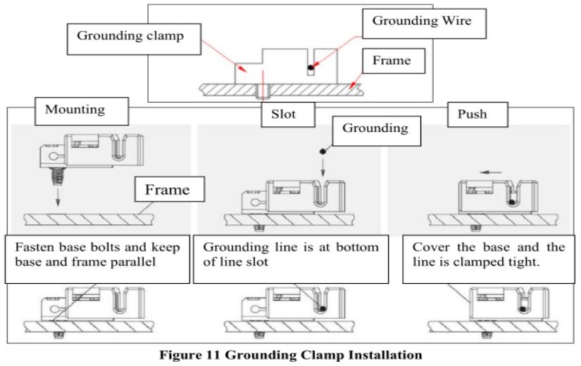
Note: TYCO. 1954381-1 (recommended) is used in figures above.
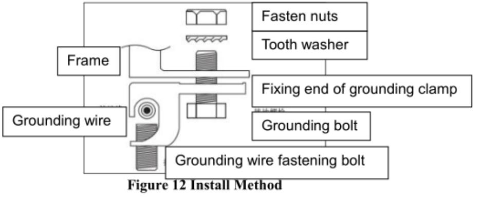
7.2 Grounding by unoccupied mounting holes
Mounting holes on modules that are not occupied can be used for installing grounding devices.
- Align grounding clamp to the frame mounting hole. Use grounding bolt to go through the grounding clamp and frame.
- Put the tooth side of the washer on the other side and fasten the nuts.
- Put grounding wires through the grounding clamp and grounding wire material and dimension shall meet requirements in local national and regional law and regulations.
- Fasten bolts of grounding lines and installation ends.
7.3 The third party grounding devices
The third party grounding device can be used for grounding of QSUN modules but such grounding shall be proved to be reliable. Grounding device shall be operated in line with stipulations of the manufacturer.
8 Operation and maintenance
WARRANTY-PERIOD RESPONSIBILITY. It is the users’ responsibility to carry out regular inspection and maintenance for modules in particular during the quality warranty period; and, inform the supplier within two weeks when modules are found to be damaged.
8.1 Cleaning
Accumulated contaminants on module surface glass will reduce the power output and lead to local heat spot, such as dust, industrial waste water and birds’ droppings. The degree of influence is determined by transparency of wastes. Small amounts of dust will affect the intensity of solar irradiation and evenness that modules received but are not dangerous and power will not be reduced remarkably in general.
During operation of modules, there shall be no environmental factors projecting shades that shelter partial or the entire module. These environment factors including other modules, module system bracket, birds, dust, soil or plants. These will significantly reduce output power. QSUN suggests that the module surface should not be sheltered in any case.
Frequency of cleaning depends on dirt accumulation speed. In normal situations, rainwater will clean the module surface and reduce the cleaning frequency. It is suggested to use damp clean water sponge or soft cloth to wipe the glass surface. Do not use acid and alkaline detergents to clean modules. Do not use tool with rough surface to clean in any case.
In order to avoid potential risk of electrical shock or burn, QSUN suggests cleaning the modules during early morning and evening with less solar irradiation and lower modules temperature especially area with high average temperature.
In order to avoid potential risk of electrical shock, do not try to clean the modules with glass damage or expose wires.
8.2 Module Appearance Inspection
Check module appearance defects visually, especially:
- Module glass cracks.
- Corrosion at welding parts of the cell main grid: it is caused by moisture into the module due to damage of surface packaging materials during installation or transportation.
- Check whether there are traces of burning on the module back plate.
- Check PV modules for signs of aging including rodent damage, weather damage, connection tightness, corrosion and grounding condition.
- Check for any shape objects in contact with PV modules’ surface.
- Check for any obstacles shielding the PV modules.
- Check for any loose or damage screws between the modules and bracket. If so, adjust and fix on time.
8.3 Inspection of connectors and cables
It is suggested to carry out the following preventive inspection once every 6 month:
- Check connector sealing and cable connection.
- Look for gap on the sealant of the terminal box and confirm whether it is cracking.
8.4 Electrical parameters of solar modules: Attachment 1
8.5 Maximum series and parallel quantities
Maximum series = system voltage / 1.25 / Voc
Maximum parallel = fuse rating / 1.25 / Isc
8.6 Connector restriction
The connector should PV-JM608, and it is stipulated that it can only match the adapted model, and cannot be mixed.
8.7 Roof installation
Cement roof; the roof also needs to have a fire-proof rate above class C (not less than the fire proof rate of modules), and the installation angle should be 22.5° less than the fire test angle to ensure that modules can meet the claimed fire-proof rate.
8.8 Altitude
The altitude of HTA is 3000m. Other altitude is normally smaller than 2000m.
9. Data form for electrical and electronic equipment/components
Temperature coefficient
| α (%/℃) — ISC | β (%/℃) — VOC | δ (%/℃) — Pmax |
|---|---|---|
| 0.04351 | -0.2562 | -0.3012 |